Draft!
Interface the ICOM R7000 10.7 MHz IF output to the Bt878a
ADC
Basis: The sound output from a receiver give us a demodulated signal (FM, AM or SSB). To be able to work on other modes we need to access to an intermediate frequency inside the receiver, just before the demodulation process. Fortunately some receivers has an Intermediate Frequency (IF) output. My ICOM R7000 ham receiver has a 10.7 MHz IF output.
Objective: Plug the IF output to the Bt878 ADC to digitalize signals up to 440KHz wide into the receiver coverage.
Method: Covert the 10.7MHz carrier to 12KHz using a downconverter kit from SAT-Service Schneider.
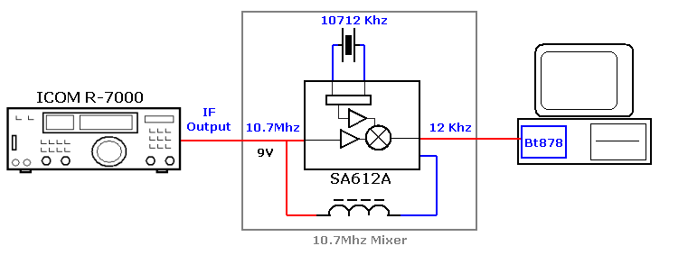
Figure 1
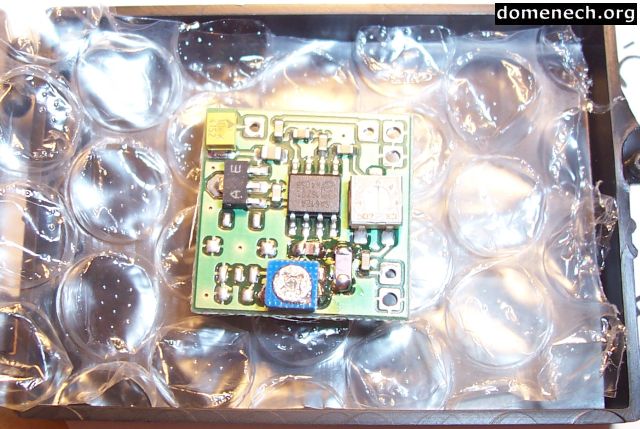
1 - Downconverter
"Universal DRM miniature mixer 10.7MHz"
Manufacturer: SAT-Service Schneider
URL:
http://www.sat-schneider.de/DRM/DRM.htm
Description:
http://www.sat-schneider.de/download/Mixerflyer.pdf
Mixer based on the Philips SA612A (datasheet) IC crystal 10712KHz local oscillator. The original design is used in receivers with 455KHz IF outputs to work with digital radio DRM (Digital Radio Mondiale).
1.1 - Power supply
The IF output from the ICOM R7000 includes a 9V DC current supply to be used externally. In the mixer power input there is a coil and a 5V regulator. That's perfect and permit us to plug the receiver IF output directly to the kit.
1.2 - Connections
- ICOM R7000 10.7MHz IF output RCA female.
- Metallic RCA male connector and RG-58 coaxial cable.
- Coaxial cable to the ZF circuit input and the cable shield to the
circuit ground (see figure 2).
- Connect together the ZF input and the Ub connection (see figure 2).
- A coaxial sound cable (or similar) from the NF output and the circuit
ground, to the ADC input.
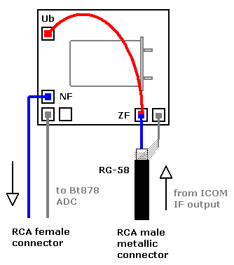
Figure 2
1.3 - Isolation
1:1 type transformer between the downconverter and the ADC.
1.4 - Adjustments and signal level
The circuit comes adjusted and ready for use. We just need to reduce at maximum the variable resistor R1 due the low level signal that comes from the ICOM receiver. The level is so low that I just can analyze high power signals (more than +9 in the S-meter) like: the FM broadcast stations or a GSM cellular phone placed close to the receiver (see spectrograms below).
One of my next project will be to obtain an amplifier to place before the mixer.
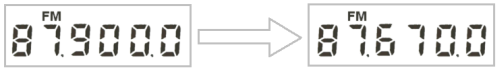
1.5 - Frequency shift
The mixer convert the IF carrier to 12 KHz. This could be enough to work with narrows signals like FMn or AM, but for wider signals we should sift the receiver frequency. For instance: To place a FM 87,9 MHz carrier as central frequency of 220KHz (440KHz/2) we must place the receiver to 87.670.0 . Does not matter what we ear in the receiver speaker, now we work with the IF.
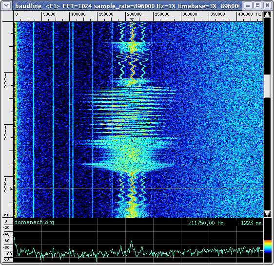
1.6 - Test
FM broadcast station spectrogram at 87.9 MHz:
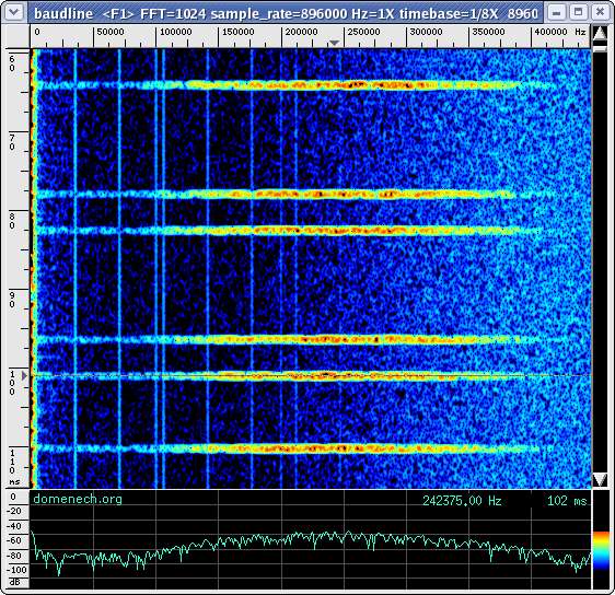
Cellular GSM frames spectrogram at 892.55 MHz:
1.7 - Interferences
![]()
- Author:
Juan Domenech Fernández
![]()
http://www.domenech.org
v0.0 25-marzo-2005
v0 25-marzo-2005