My First Software Defined Radio (SDR) Receiver - 1st Section
Capture Stage
![]()
1st Section - Capture Stage
2nd
Section - Downconverter
3rd
Section - Demodulation
Appendix - Spectrogram
Basis: You can find applications to use your PC as a demodulator thru the analog to digital converter (ADC) in the sound card, using first a downconverter or some kind of radio stage. Using a more wide ADC we can do the same function without need any previous electronic stage, I mean: the downconverter stage, the filters and the demodulation process become programs inside the PC. And this is, approximately, Software Defined Radio (SDR).
With the Bt878's ADC in the 896000 Sps mode (as shown in my previous article btaudio.c module modification to get 896000 Samples per second with the Bt878A ADC), we can digitalize signals up to 443 KHz. This permits us to do a direct radio reception within this bandwidth.
Objectives: First: To learn SDR. Second: find out whether we can do direct radio reception with just the Bt878 and a PC.
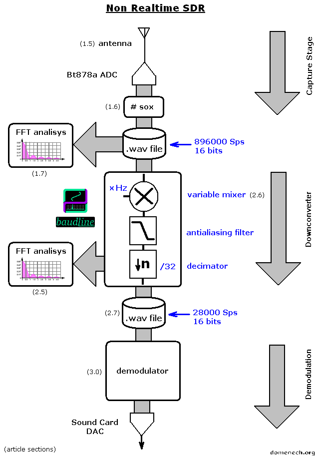
Method: The following figure shows the blocks of the Non Real-time experimental SDR process. Each element will be explained in this article and its sections.
1.1 - Why Non Real-time?
Just a power problem. I do my experiments with an old AMD 400 MHz PC. Thanks to the Bt878A architecture, the capture process takes few CPU (8% in my case) and we have to consider that we are working with 896000 Sps 16 bits and this are 1.7 MBytes/second. The problem begins when we run another application at the same time and it takes all the available CPU. Then the btaudio module can't get enough CPU cycles to read the buffer (that is 8 KBytes big) and it causes buffer overruns. This creates gaps in the stream, damaging it for further processes.
1.2 - I have a powerful machine. Can I work in Realtime?
I think so... tell me about it :) In the following section I'll explain how to do it using Unix pipes.
1.3 - Which radio signals I can get?
I'll like to make clear that this article is just an experiment and it has no sense to use this method as a daily use radio receiver. My objective is to learn and to show what I've learned.
We can tune up to 443 KHz and this is all the LF band and a piece of the MF band. Inside the LF there is the popular Long Wave, where we still can find commercial broadcast stations. There is also a lot of radio beacons, time signals and a bunch of exotic utility stations.
Capture Stage
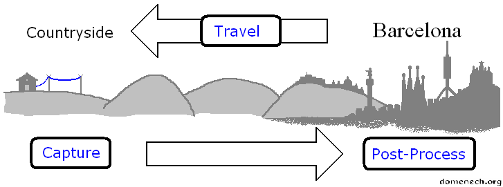
1.4 - Countryside weekend
After trying several times at my flat in Barcelona, I didn't manage to get a radio signal with a known origin. The problem was obvious: low signal level at the input. I was unable to use an antenna bigger than 4 meters and I'm also surrounded by buildings just in the middle of the city.
During a weekend at my father's house (Tarragona, Spain), I'd setup my test PC, a long antenna and I did some captures.
One interesting option in SDR is that we can analyze the signal afterwards. We can "move" thru the signal in any axis, I mean: we can analyze a carrier in some frequency during some minutes and then go back and do it again or jump to another frequency to find out what was happening just at the same time when we were processing the previous signal. The only limit is our hard disk space.
1.5 - The antenna
Following image shows my the antenna diagram. The simplest as possible.
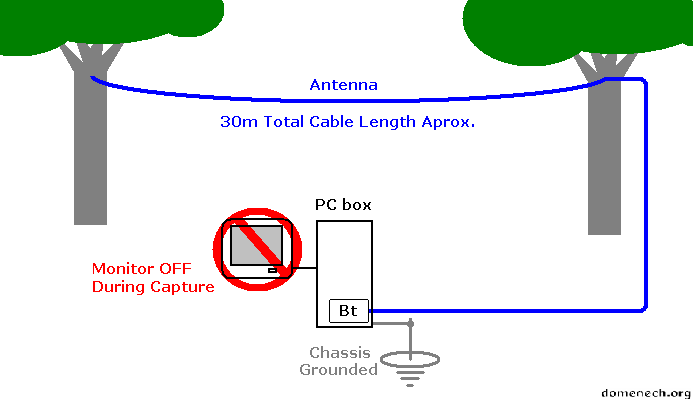
The Bt878A's ADC is connected to a typical electric cable, 30 meters long. The ADC's ground pin is not connected. The PC chassis is ground connected thru a thickness cable and a long nail or a big screwdriver. The PC screen should be turn off during the capture stage. In theory, as longest cable, better antenna. To learn more (Google).
1.6 - Capturing using the SOX command
The btaudio module loaded in memory with dec = 2 (as previously explained) to digitalize with 896000 Sps.
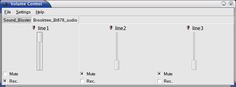
From Xwindows we should rise the ADC's gain at maximum, using the volume control:
Next:
# sox -r 896000 -w -t ossdsp /dev/dsp2 -t .wav radio-capture-896000.wav
(note: the /dev/dsp2 parameter is hardware dependent)
The PC screen turned off during the capture. We let the capture command run during some seconds and stop it using CTRL+C. It's important to close any unnecessary programs to avoid to use the hard disk at the same time. Remember: 896000 Sps with 16 bits = 1.7 MBytes/second.
1.7 - Exploring the spectrum
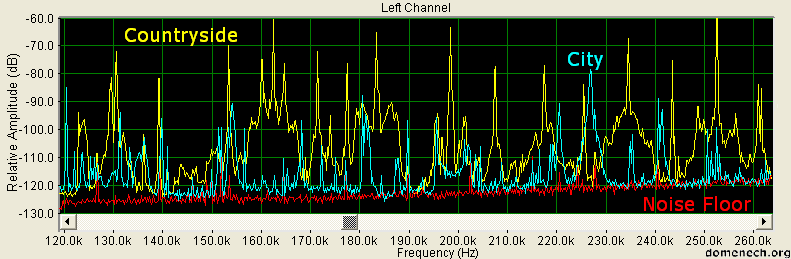
Let's find out if my antenna likes trees. The following image is the recent captured signal spectrum (yellow line). The cyan line belongs to a signal captured in the city and the red one is the ADC's "noise floor" (previously explained). Obtained with Spectraplus and Average = 10. We can easily see a better level almost in all the bandwidth. Cool.
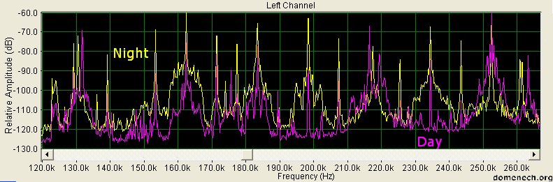
I did a couple of captures. One during the day (12:30h) and another at night (00:30h). I compare both of them in the following image. Yellow line is the night and the purple line the day. We can see that night's signal is better.
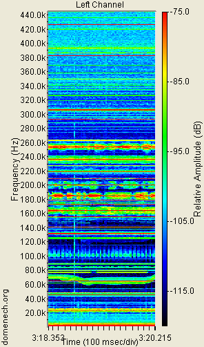
Following image is a spectrogram of the signal we can get with the Bt878's ADC in the 896000 Sps mode. The picture was made by getting several spectrograms an putting them together with a graphic editor.
Click in the image to see the whole version. Warning: Is a 3 Mbytes image.
We can observe several carriers. Specially visible are: The broadcasting Long Wave band, between 150 and 260 KHz., time signals between 60 and 80 KHz., a mysterious signal which moves in this band, the radio location system LORAN-C at 100 KHz. and some radio beacons between 280 and 430 KHz.
Those radio beacons will be very useful in next section to make my first radio reception experiment.
1.8 - Radio Beacons
I think that a radio beacon is the simplest radio signal we can find, then, are perfect for the first reception.
A radio beacon is a Morse signal (CW) that repeats a callsign in regular intervals from a fixed frequency and location. Its mission is to help the ships to track its position on a map. Today, the massive use of GPS, makes this tool obsolete but a lot of them are still operative and we can easily "read" them with a spectrogram.
After the analysis of the captured signal, I've received and identified these eight radio beacons:
| Frequency: 285,8 KHz. | Callsign: AS AS | Pause: 50 Seconds | Location: Castelló |
|
|
|||
| Frequency: 293,8 KHz. | Callsign: MH MH | Pause: 60 Seconds | Location: Mao |
|
|
|||
| Frequency: 294,3 KHz. | Callsign: FI FI | Pause: 60 Seconds | Location: Cala Figuera |
|
|
|||
| Frequency: 338,4 KHz. | Callsign: QA QA | Pause: 2 Seconds | Location: Barcelona |
|
|
|||
| Frequency: 356,4 KHz. | Callsign: SGO | Pause: 10 Seconds | Location: Sagunt |
|
|
|||
| Frequency: 380,4 KHz. | Callsign: VNV | Pause: 6 Seconds | Location: Vilanova i La Geltrú |
|
|
|||
| Frequency: 384,4 KHz. | Callsign: ADX | Pause: 4 Seconds | Location: Andraitx |
|
|
|||
| Frequency: 424,6 KHz. | Callsign: RES | Pause: 18 Seconds | Location: Reus |
|
|
|||
I was able to find the correspondence between the callsigns and the beacons location thanks to this great collection: http://www.xs4all.nl/~cisquet/NDB.htm
This picture shows the result:
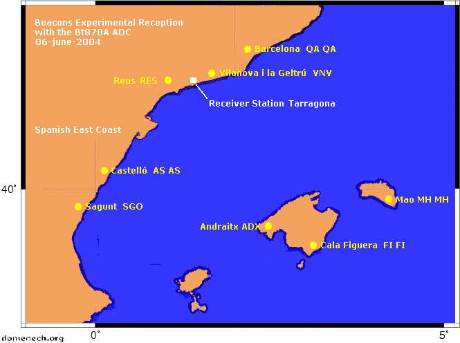
I think that all this make sense. My proximity to the sea permits me to receive radio beacons up to 250 Kilometers from me, from the near island Mallorca and Menorca.
| Update 10-2004 eMail from Michael Oexner As NDBs are my special
area of interest I'd like to provide some additional info on frequencies,
offsets and coordinates. It seems that the frequencies that you show in your
screenshots are a little bit off with respect to the listed carrier
frequencies. |
Now we have in our hard disk a portion of the radio spectrum. In the next section we will manipulate it.
->> 2nd Section - Downconverter ->>
- Author:
Juan Domenech Fernandez
![]()
http://www.domenech.org
v0.3 14-november-2004
v0 21-june-2004