![]()
Analog to Digital Converter with 16 bits and 448000 Samples per second based in the Bt878A
|
|
 |
Update! 08-2005
ALSA
support for the Bt878a and Fedora Core 4
Update! 05-2004
Article with modification to get 896000 Sps
Basis: The power of the actual Personal Computers (PC), give us the possibility to analyze and manipulate complex analog signals, but first we need to digitalize them using an Analog to Digital Converter (ADC). With any common PC, we can easily digitalize analog signals with the sound card that it includes, but with the limitation of 44000 Samples per second (Sps) or 96000 Sps in some State-Of-The-Art sound cards. Following Nyquist, this permits us to get 48Khz width signals, in the best case. This frequency is enough for sound experimentation, but isn't to explore a wider spectrum or for detailed analysis of low frequency signals.
Objective: To get an ADC what permits us digitize at the higher frequency as possible, using "off-the-shelf" hardware.
Method: We will use the low frequency ADC that comes with the Bt878A chip in a typical PC-TV card.
Warning: This article describe actions that
  should be done only by experienced people in electronics and potentially can damage
  your equipment.
|
Preparation:
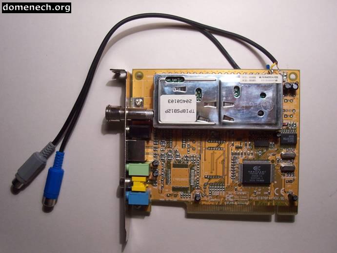
1 - Equipment used:
- PC-TV card with tuner, brand: BestBuy, model: EasyTV (build by
Prolink, model: PV-BT878P+ Rev 9D), Conexant 878A Fusion chip
based and the Philips PAL_BG FI1216 tuner.
- Standard PC with Creative sound card.
- Linux Mandrake 9.1
- 1µF capacitor (not polarized).
- RCA female audio connectors and coaxial audio cable.
- Various tools: cable cutter, soldering iron, etc.
2 - What is the Bt878A chip?
It's the successor of the famous Bt848. When Brooktree (now Conexant) designed this new device, they included a build-in low frequency ADC, with the objective of digitalize the sound signals (and audio sub carriers) coming from the tuner to be later on demodulated by software (obtaining the FM Stereo, TV Stereo, RDS, MTS, etc.) using the operating system driver. Unfortunately no manufacturer has used this possibility (as far I know) and they simply use the ADC to get mono sound from a tuner into the PC (in the best case).
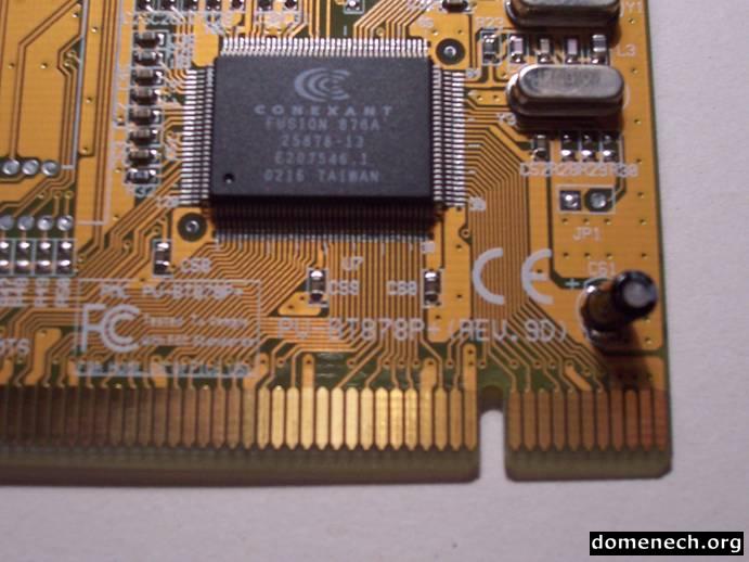
3 - My TV card it's a "878" but not a Brooktree chip.
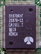 We can find it manufactured by Rockwell (datasheet download page) |
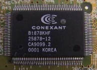
by Conexant, with the Bt878KHF package. (datasheet download page) |
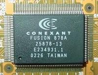
or the Conexant Fusion 878A (datasheet download page), the most typical one. |
4 - Which are the characteristics of this ADC?
Conexant's datasheet says:
"1.2.6 Audio DMA Channels
The audio channel delivers 8-bit or 16-bit digital samples of a digital
frequency-multiplexed analog signal to system memory in packets of DWORDs.
A RISC program controls the audio DMA Program Initiator. The flow of audio data
and audio RISC instructions is completely independent and asynchronous to the
flow of video data and video RISC instructions.
Since the audio data path operates in continuous transfer mode (no sync gaps),
both the analog and the digital audio inputs can be used for other data capture
applications. The analog input offers 360 kHz usable BW at 8 effective bits or
100kHz usable BW at 12 effective bits. The digital input offers up to 20 Mbps
for the parallel mode and 40 Mbps for the serial mode."
Gerd Knorr, says in his btaudio's README file:
"The analog mode supports mono only. Both 8 + 16 bit. Both are _signed_int, which is uncommon for the 8 bit case. Sample rate range is 119 kHz to 448 kHz. Yes, the number of digits is correct. The driver supports downsampling by powers of two, so you can ask for more usual sample rates like 44 kHz too."
About this document, we conclude what: The Bt878A's ADC can work with 8 and 16 bits samples, 119000 and 448000 Sps and one channel (monaural) without any kind of conversion or additional hardware.
5 - My PC-TV board use a Bt878A but is not a "PV-BT878P+ Rev 9D". Can I use it anyway?
You need to take a closer look to your board to find out how the card manufacturer uses the ADC input pins.
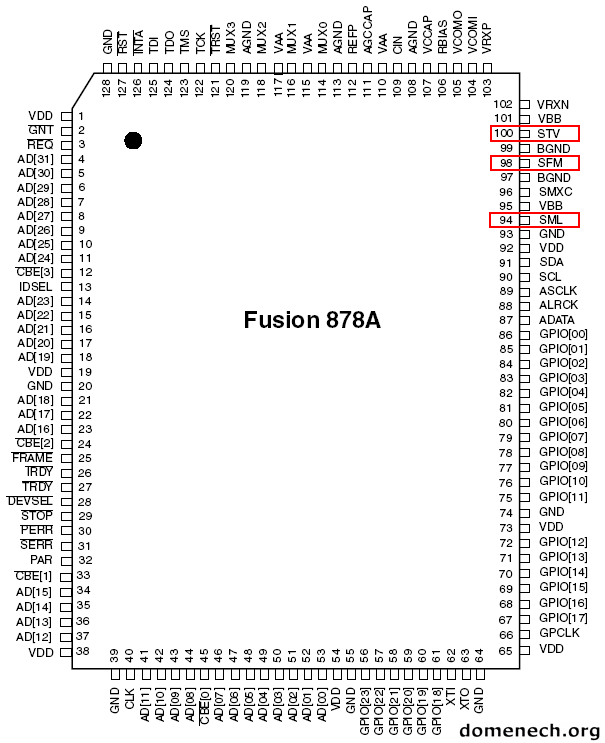
Datasheet Conexant Fusion 878A
The ADC pins are:
|
Pin # |
Signal |
Description |
|
100 |
STV I |
TV sound input from TV tuner. |
|
98 |
SFM I |
FM sound input from FM tuner. |
|
94 |
SML I |
MIC/line input. |
|
96 |
SMXC A |
Audio MUX anti-alias filter RC node. Connect through 68 pF capacitor to BGND. |
|
106 |
RBIAS A |
Connection point for external bias 9.53 kΩ 1% resistor. |
|
105 |
VCOMO A |
Common mode voltage for the audio analog circuitry. This pin should be connected to an external filtering 0.1 µF capacitor. |
|
104 |
VCOMI A |
Common mode voltage for the audio analog circuitry. This pin should be connected to an external filtering 0.1 µF capacitor. |
|
107 |
VCCAP A |
Audio analog voltage compensation capacitor. This pin should be connected to an external filtering 0.1 µF capacitor. |
|
103 |
VRXP A |
Audio input circuitry reference voltage. This pin should be connected to an external filtering 0.1 µF capacitor. |
|
102 |
VRXN A |
Audio input circuitry reference voltage. This pin should be connected to an external filtering 0.1 µF capacitor. |
Our pins are the #100, #98 and the #94, which are the ADC signal inputs. In my board the #94 is not used, the #100 and #98 are connected to the same copper trace and from there to the tuner sound output. It's recommended to check if the external voltage reference capacitors are installed because they are needed by the ADC conversion.
The Bt878A includes an internal multiplexer (mux) to select the active sound input (TV, FM or MIC) the same way the internal video mux selects the active video signal (Tuner, S-Video or Composite).
It's important not to confuse this mux with the external mux that the PV-BT878P+ includes using a Philips HEF4052B (datasheet download page) driven by the GPIO port.
All the instructions included here are only directly applicable to the Prolink PV-BT878P+ 9D board, but we can successfully use another card if we study it in detail and apply this concepts.
If your board does not use the ADC inputs (they are not connected to any copper track) I suggest not to use it, because it's very difficult to solder in a SMD chip and you will need tools that are hard to find.
Installation:
1 - First we need a working Linux with 2.4 Kernel and sound support:
I've used a Mandrake 9.1
# uname -a
Linux lab 2.4.21-0.13mdk #1 Fri Mar 14 15:08:06 EST 2003 i586 unknown unknown GNU/Linux
The main reason to use Linux to drive the ADC is that I didn't find drivers for Microsoft Windows which allowed me to use the Bt878A's ADC like an operating system sound device. If anyone sends me information about this point, it will be very appreciated. (This doesn't mean I don't like to work with Linux... I like it very much :)
2 - Check whether the sound module is up and running:
# lsmod
Module                  Size  Used by    Not tainted
af_packet              14952   0  (autoclean)
ide-floppy             15580   0  (autoclean)
ide-tape               48304   0  (autoclean)
ide-cd                 33856   0  (autoclean)
cdrom                  31648   0  (autoclean) [ide-cd]
floppy                 55132   0
ne2k-pci                6752   1  (autoclean)
8390                    7916   0  (autoclean) [ne2k-pci]
supermount             15296   2  (autoclean)
videodev                7872   0
sb                      9044   0  (unused)
sb_lib                 41454   0  [sb]
uart401                 8196   0  [sb_lib]
sound                  70644   0  [sb_lib uart401]
soundcore               6276   0  [sb_lib sound]
rtc                     8060   0  (autoclean)
ext3                   59916   2
jbd                    38972   2  [ext3]
3 - Check whether the first sound device has been created:
# ll /dev/dsp*
lr-xr-xr-x    1 root     root            9 Jan  6 12:26 /dev/dsp -> sound/dsp
lr-xr-xr-x    1 root     root           10 Jan  6 12:26 /dev/dspW -> sound/dspW
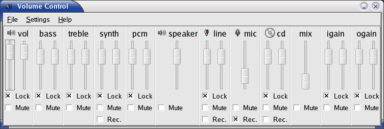
4 - In Xwindows, we open the sound mixer and check whether it shows our sound card options:
5 - We play a test sound and we should ear it thru our speakers.
For instance:
# sox -t .wav /usr/share/licq/sounds/fun/Online.wav -t ossdsp /dev/dsp
6 - Install your PC-TV card inside the computer.
Just connect the TV antenna cable. Do not connect any sound cable to the card.
7 - bttv (0.7.107) installation
Due some problems during the bttv module installation, this section has been simplified. We will jump directly to the btaudio module load, ignoring the bttv compilation.
8 – btaudio module load
btaudio is the kernel module who permit us to use the Bt878's ADC like a sound device into the Linux (Thanks Gerd!). The Linux release that I'm using (Mandrake 9.1) includes this module in /lib/modules/2.4.21-0.13mdk/kernel/drivers/sound/btaudio.o.gz and we can proceed to load it.
# insmod btaudio debug=1
If every thing goes right we should read this in the kernel log:
#tail -100f /var/log/syslog | grep btaudio
Apr 17 19:08:57 lab kernel:
btaudio: driver version 0.7 loaded [digital+analog]
Apr 17 19:08:57 lab kernel: btaudio: Bt878 (rev 17) at 00:09.1, irq: 10,
latency: 32, mmio: 0xde001000
Apr 17 19:08:57 lab kernel: btaudio: using card config "default"
Apr 17 19:08:57 lab kernel: btaudio: registered device dsp1 [digital]
Apr 17 19:08:57 lab kernel: btaudio: registered device dsp2 [analog]
Apr 17 19:08:57 lab kernel: btaudio: registered device mixer1
9 - Module compilation
If our Linux doesn't include a btaudio already compiled, we can try to compile it yourself. You can get the source from here btaudio-0.7.tar.
"Un-tar", move into the directory and compile:
# gcc -O2 -DMODULE -D__KERNEL__ -c btaudio.c -isystem /lib/modules/2.4.21-0.13mdk/build/include/
Compress and move the module to its folder:
# gzip btaudio.o
# mv btaudio.o.gz /lib/modules/2.4.21-0.13mdk/kernel/drivers/sound/
# depmod -a
In my system I got this message after depmod command "depmod: *** Unresolved symbols in btaudio.o.gz" but I just ignore it. We can load the module now:
# insmod btaudio debug=1
If we read this error message:
./btaudio.o: kernel-module version mismatch
./btaudio.o was compiled for kernel version 2.4.21-0.13mdkcustom while this
kernel is version 2.4.21-0.13mdk.
We should edit the /usr/src/linux/include/linux/version.h file and replace '#define UTS_RELEASE "2.4.21-0.13mdkcustom"' by '#define UTS_RELEASE "2.4.21-0.13mdk"' and repeat the compilation step.
10 - We now check that we have two new sound devices:
# ll /dev/dsp*
lr-xr-xr-x    1 root     root            9 Jan  6 13:54 /dev/dsp -> sound/dsp
lr-xr-xr-x    1 root     root           10 Jan  6 14:04 /dev/dsp1 -> sound/dsp1
lr-xr-xr-x    1 root     root           10 Jan  6 14:04 /dev/dsp2 -> sound/dsp2
lr-xr-xr-x    1 root     root           10 Jan  6 13:54 /dev/dspW -> sound/dspW
The /dev/dsp1 is the I2S digital audio interface and the /dev/dsp2 is the Bt878A's ADC, the one we will use.
11 - The sound mixer detects a new sound device: "Brooktree_Bt878_audio"
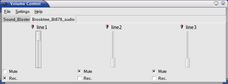
We select Rec, increase a bit the recording level in Line1 and leave muted Line2 and Line3 as showed in the image.
12 - Audio_in test:
# sox -w -r 32000 -t ossdsp /dev/dsp2 -t ossdsp /dev/dsp
We should ear a strong audio noise in the speakers connected to our sound card. That's the audio signal that comes from the tuner (it's activated as soon the PC boots) the one we are digitalizing and sending to the sound card. We are doing it with our Bt878! :)
We can use a TV software program (like xawTV) to tune a TV channel and use its sound as test (instead of noise). It's not necessary to see perfectly the television image. Leaving the sox command running in a shell, we will hear the channel's sound.
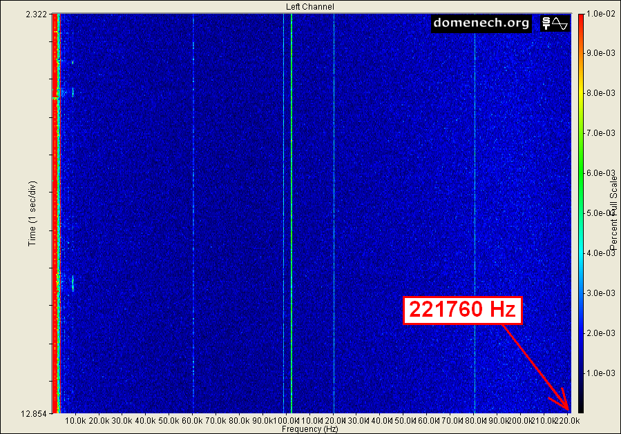
13 - Audio capture test:
# sox -w -r 448000 -t ossdsp /dev/dsp2 -t .wav sound.wav
-w            16 bits
-r            448000 Sps
/dev/dsp2     ADC analog input
-t .wav       audio file format
Analyzing the sound file using Audacity (freeware), we can see to the left the audible sound zone (up to 20Khz) that comes from TV signal. But there are also signals at higher frequencies (noise) which are the best proof that we are digitalizing much higher, up to 224Khz approximately.
Modifications
1 - External signal input.
The following connections are available in the PV-BT878P+ 9D:
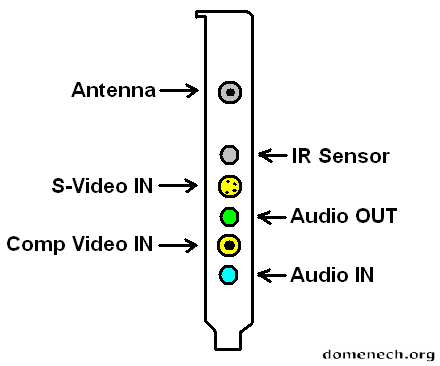
It seems that the AudioIN connector allows us to put a signal into the board and then into the Bt878A low frequency ADC, but is not so. Inexplicably, the AudioIN task is just to give us this signal back to the AudioOUT connector thru the Philips mux, as the next diagram shows. I'd like to be wrong but... :(
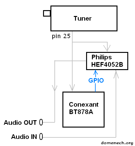
Summarizing: Using the external mux we can choose between the tuner audio or the AudioIN signal and send it out thru the AudioOUT connector, but this external signal will never reach the ADC.
2 - Access to the tuner output.
The mod concept is: To inject an external signal into the ADC using the audio tuner output in the #25 pin, cutting this pin first and wiring it outside our PC box. We will wire outside also the tuner audio output to be able to use this resource in the future.
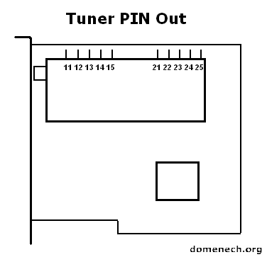
Tuner Philips FI1216 Datasheet
|
SYMBOL |
PIN |
DESCRIPTION |
|
VT |
11 |
tuning voltage (monitor) |
|
VS |
12 |
supply voltage tuner section +5 V |
|
SCL |
13 |
I2C-bus serial clock |
|
SDA |
14 |
I2C-bus serial data |
|
AS |
15 |
I2C-bus address select |
|
n.c. |
21 |
not connected |
|
2nd IF sound output |
22 |
second IF sound output |
|
CVBS |
23 |
Composite Video Baseband Signal output |
|
VIF |
24 |
supply voltage IF section +5 V |
|
AF sound output |
25 |
AF sound output |
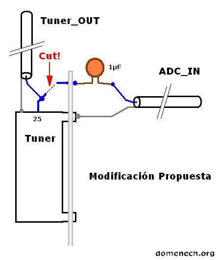
3 - Steps:
- Uninstall the PC-TV board from the PC
- Cut (carefully!) the tuner sound output at pin number 25.
- Solder in the old #25 pin connection on the PCB surface a 1µF capacitor
to stop the DC, use the shortest capacitor legs as you
can.
- Solder between the capacitor and the board ground a coaxial sound cable (the
cable shield connected to ground).
- I suggest to use as ground connection the leg of the tuner chassis that goes
thru the PCB.
- Solder a female RCA audio connector (or the kind you prefer) at the
cable end. We can call this input: ADC_IN.
- Solder between the #25 pin (now is free in the air) and ground
another coaxial audio cable.
- Solder a female RCA audio connector (or the kind you prefer) at the
cable end. We can call this output: Tuner_OUT.
- Install the board, leaving the cables outside the PC box.
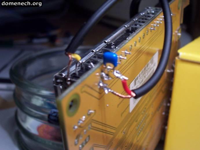
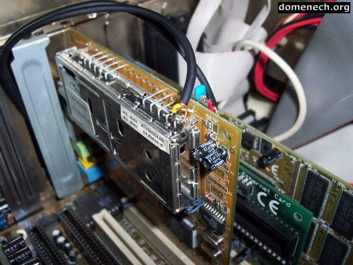
Here there are some pictures where you can check how bad I am soldering :)
 |
 |
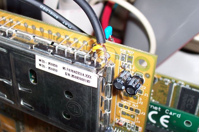 |
 |
 |
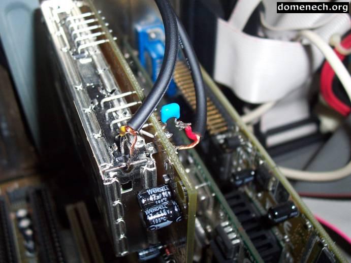 |
4 - Test.
Once the card is installed and the system is running we will do a test to find out if the soldering is right.
With a standard male RCA audio cable, we connect together ADC_IN and Tuner_OUT and repeat the step: Installation-12. We should ear again a noise signal (or a sound if we have a TV channel tuned) what comes from the tuner, but now it's going out from and into our PC.
If the test is ok, we have ready our homebrew 16 bits and 448000 Sps ADC.
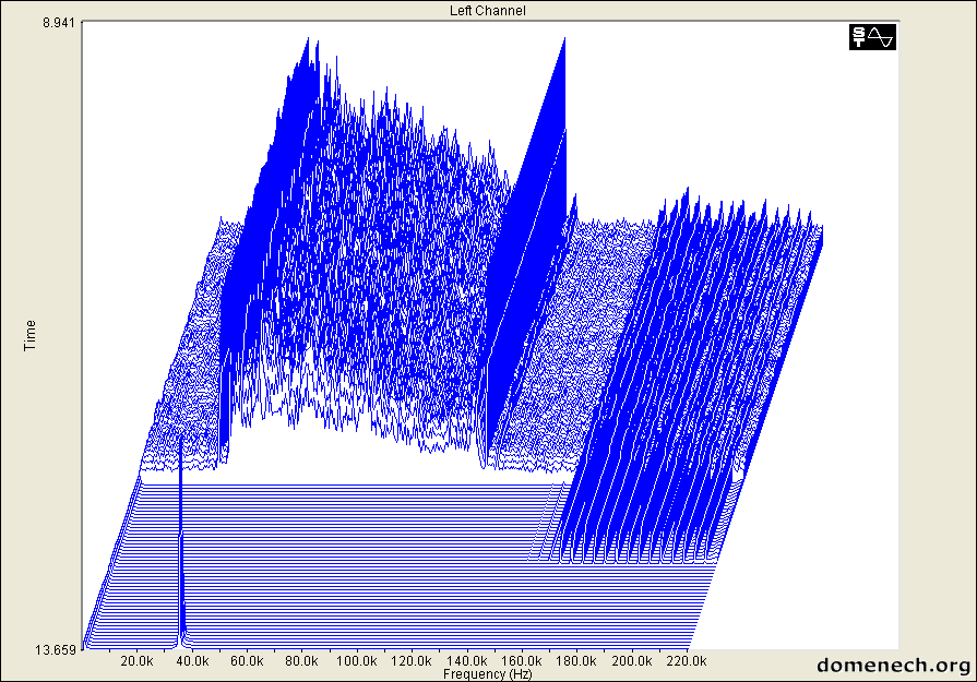
5 - Interferences.
Now it's interesting to do a little test to explore the "neighborhood" we will have always in our experiments: The inner computer interferences.
Doesn't matter how good soldering we are or how short the unshielded copper we leave, we will suffer some interferences due to the amount of electronics around the Bt878A.
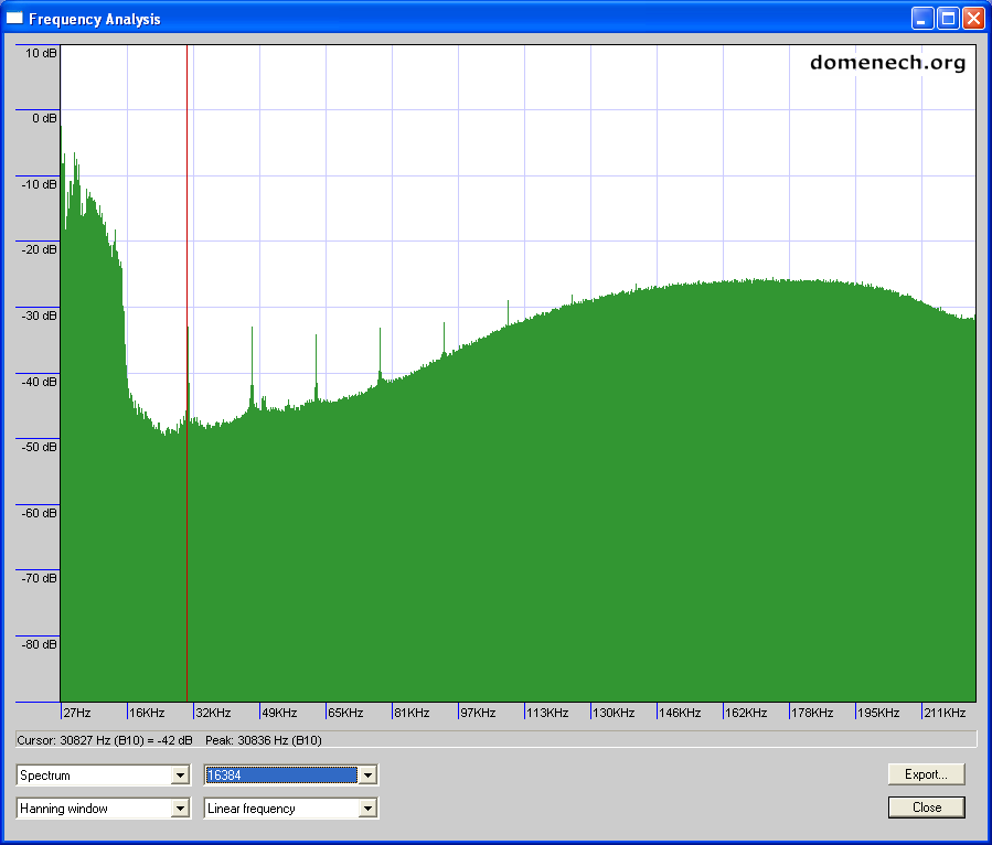
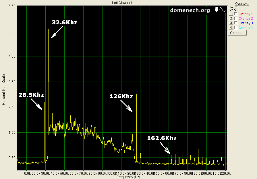
This is a graphic generated by SpectraPLUS (30 days demo) for Microsoft Windows, using a signal obtained from the Bt878A without anything plugged at ADC_IN and amplified by software with the parameter Plot_Top = 0.010
In my case, I observe strong signals between 0 and 2000Hz and some "carriers" at 60, 98, 102, 120.4 and 180.4 Khz.
In theory, different PC models create different interferences and is important to know them to avoid getting wrong results in our experiments. But don't worry, if you have some load plugged and the incoming signal is strong enough these interferences almost disappear.
6 - Now what?
It's your turn, now we don't have the limit of our poor sound card. I'm exploring new areas and finding really interesting things and I'll public new articles soon.
Anyone can guess from which kind of signal this spectrum comes? (click for zoom)
Happy sampling! :)
Update! 08-2005
ALSA
support for the Bt878a and Fedora Core 4
Update! 05-2004
Article with modification to get 896000 Sps
- Credits:
Gerd Knorr
Luis Padilla
Iban Cardona
- Author:
Juan Domenech Fernandez
![]()
http://www.domenech.org
v1.8 01-may-2006
v0 19-january-2004